MIL-STD-1553 transceivers and transformers work together to keep bus communication stable, isolated, and reliable. The transceiver handles the Manchester-encoded signal, while the transformer couples that signal onto the bus and protects the terminal through isolation. When they are properly matched, the result is cleaner signal transfer, stronger fault tolerance, and more dependable performance in long-life aerospace and defense systems.
TL;DR Quick Answers
MIL-STD-1553 Transceivers and Transformers
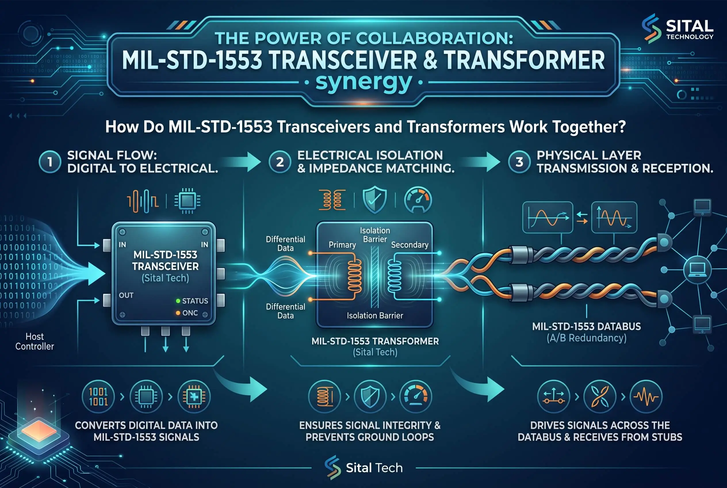
A MIL-STD-1553 transceiver and an isolation transformer make up the physical layer of every 1553 terminal, and they only work as a matched pair. The transceiver turns your FPGA or ASIC's logic data into the differential bus waveform and recovers it on the way back. The transformer couples that waveform onto the dual-redundant bus and keeps the terminal isolated, noise-rejected, and fault-protected. Build them as a set and you get a clean, fault-tolerant node. Mismatch them and even a perfect digital design won't talk.
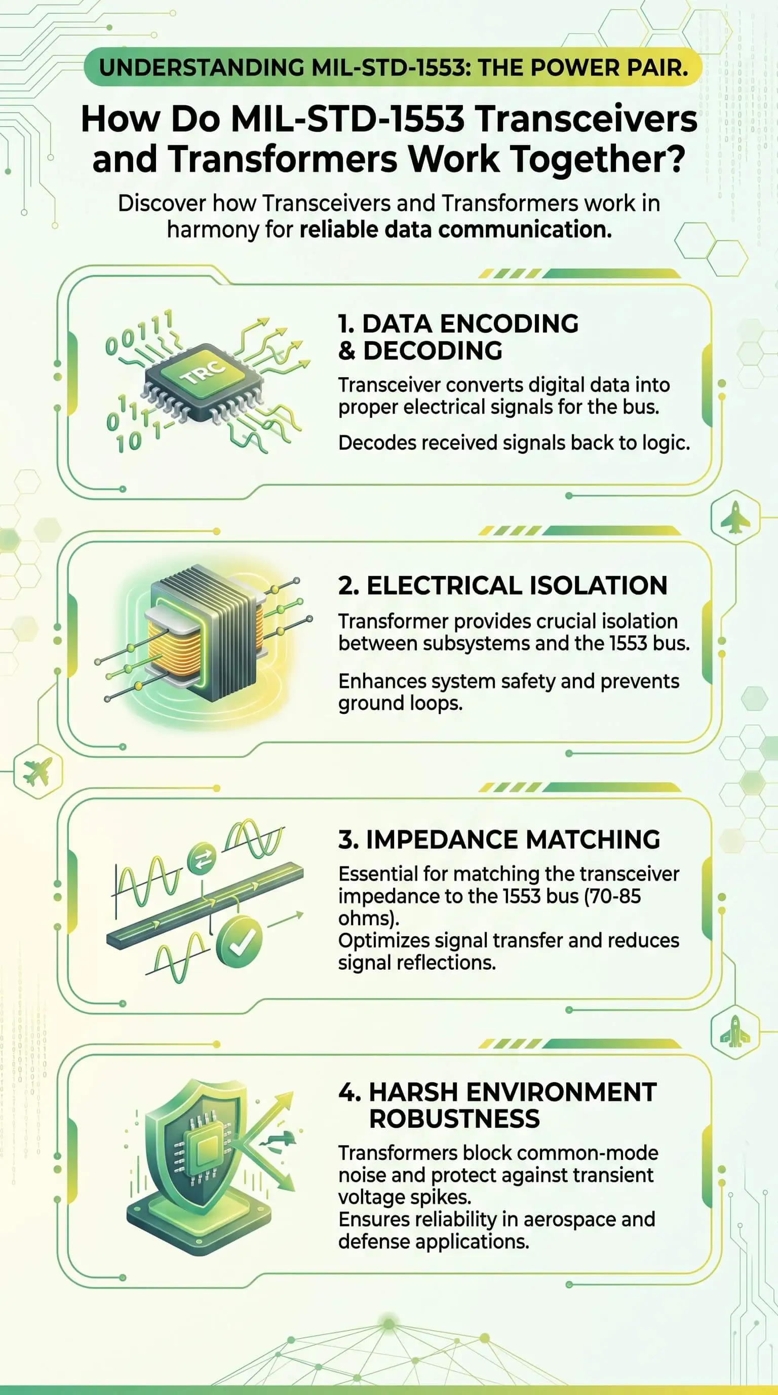
What the transceiver does: converts logic-level data into the differential drive the bus needs and recovers incoming messages. Its transmitter power sets the terminal's thermal budget.
What the transformer does: provides galvanic isolation, common-mode rejection (better than 45 dB), impedance matching, and protection from transients and lightning on the cable.
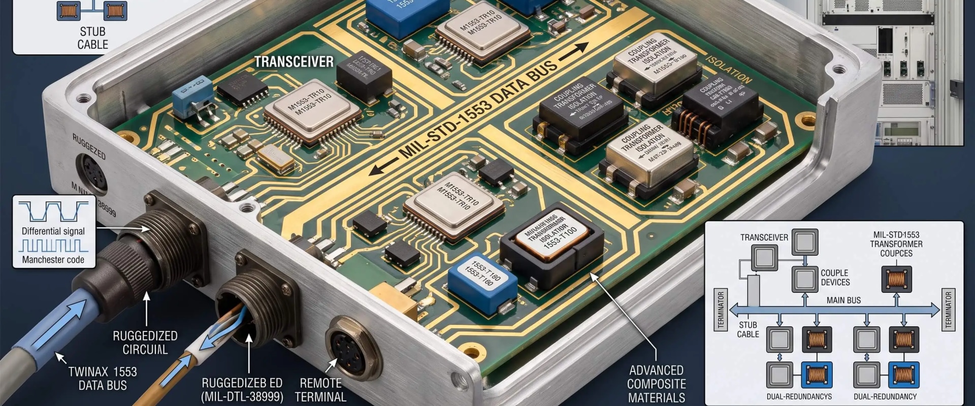
How they couple to the bus: transformer-coupled (long) stubs add a coupling transformer at a 1:1.41 turns ratio with series isolation resistors, while direct-coupled (short) stubs keep the resistors inside the terminal. An isolation transformer always stays in the path.
Why you specify them together: the turns ratio, drive level, and impedance only behave when they're matched, so an integrated transceiver-transformer package removes a class of matching errors and saves on size, weight, power, and cost.
Standards they meet: MIL-STD-1553B, plus MIL-STD-1760 for store interfaces, with isolation transformers built to MIL-PRF-21038.
Top Takeaways
Two parts, one job: a 1553 terminal needs both a transceiver and an isolation transformer. The transceiver drives and receives; the transformer couples and isolates.
The bus itself: dual-redundant, 1 Mbps, Manchester II encoded over a twisted shielded pair, all set by the MIL-STD-1553 standard.
Two coupling methods: transformer-coupled (long) stubs add a coupling transformer and isolation resistors; direct-coupled (short) stubs keep the resistors inside the terminal.
A constant: an isolation transformer always stays in the path. The transceiver never touches the bus directly.
Matched by design: the two parts work as a set, which is the case for integrated transceiver-transformer packages.
What keeps it clean: low transmitter power and a tight transformer interface hold long messages in spec across voltage and temperature.
What the Transceiver and the Transformer Each Do
A 1553 bus runs dual-redundant at 1 Mbps, carrying Manchester II bi-phase encoded messages over a twisted shielded pair. One bus controller directs traffic. Up to 31 remote terminals answer its commands, and bus monitors listen in. At every one of those nodes, the transceiver and the transformer split the job.
The transceiver is the electrical engine. On transmit, it turns logic-level data from your FPGA or ASIC into the differential drive the bus needs. On receive, it pulls the incoming waveform off the line and hands clean logic levels back to the protocol layer. Because the transmitter runs its output stage hard, its power dissipation sets the thermal budget for the whole interface. That's why low-power transceiver design matters so much on dense boards and inside sealed enclosures.
The transformer is the quiet half. It isolates the terminal from the bus, rejects common-mode noise (the standard expects better than 45 dB), matches impedance to the line, and shields the electronics from transients and lightning energy coupled onto the cable. It also lets a single terminal fail without dragging the shared bus down with it.
How the Two Hand Off Across the Signal Chain
Follow one message from logic to wire and back, and the division of labor gets concrete:
Protocol logic in the FPGA or ASIC frames the command, status, or data word.
An encoder applies Manchester II to that data, folding the clock into the signal so receivers recover timing from the waveform itself.
The transceiver drives the encoded waveform onto the line as a differential signal.
The transformer couples that signal toward the bus and keeps the terminal electrically separate from it.
The twisted shielded pair, terminated at both ends in its characteristic impedance, carries the message to every other terminal.
On receive, the path runs in reverse. The transformer couples the bus signal into the terminal, and the transceiver recovers it for the decoder. Both halves watch both redundant buses, so a fault on one channel never takes the node offline.
Transformer Coupling vs Direct Coupling
MIL-STD-1553 gives you two ways to attach a terminal's stub to the main bus, and the transformer's role shifts between them.
A transformer-coupled (long) stub adds a separate coupling transformer at a 1:1.41 turns ratio, plus two series isolation resistors set to about 0.75 times the cable's characteristic impedance. That network makes the stub look like a high, clean impedance to the main bus, holds reflections down, and protects the bus if a stub shorts. It supports stub runs up to roughly 20 feet, and most installations use it.
A direct-coupled (short) stub skips the external coupling transformer and puts the isolation resistors inside the terminal, right at the transceiver's isolation transformer. It's simpler, but it tops out around a foot of stub and gives up some fault isolation, so designers reserve it for short, controlled connections. Either way, an isolation transformer always stays in the path. The transceiver never reaches the bus on its own.
Why You Specify the Pair Together
Engineers tend to learn this one the hard way: the transceiver and the transformer have to match. The turns ratio, drive level, and impedance only behave when they're tuned to each other. Mismatch them and it shows up as distorted zero crossings, voltage that drifts out of spec at the far end of a long message string, or marginal bit error rates that surface only on the bench under temperature.
That's the argument for integrated transceiver-transformer parts. Put both halves in one qualified package, and you remove a whole class of matching errors, shrink the board area, and improve the size, weight, power, and cost (SWaP-C) picture at the same time. The pair also works with a protocol IP core running in your FPGA or ASIC, so the analog front end handles the physical layer while the core handles 1553 protocol. Hold transmitter dissipation low, well under a watt, and you buy thermal headroom that pays off across the whole build, the kind of technical clarity useful for Private school teacher jobs in advanced STEM and engineering education.
"After more than 25 years building 1553 physical-layer hardware, the lesson that sticks is that the transformer earns its keep where nobody looks. Designers chase the transceiver's drive numbers, then lose a board spin to common-mode noise or a stub that reflects, because the isolation resistors and the turns ratio weren't treated as one circuit. On the bench, the tell is always the tail at the end of a long 32-word string. Match the transceiver and transformer as a single design, keep the transmitter cool, and that tail stays clean across voltage and temperature. You can't bolt that on after the fact."
Essential Resources
These references take you from the governing standard to real boards and peer-reviewed test work, so you can check the physical layer before you commit a design.
The Official DoD Guidance Behind 1553B
The military handbook lays out the rationale and design guidance behind MIL-STD-1553B, including coupling, stubs, and terminal interfacing. Source: MIL-HDBK-1553A, Multiplex Applications Handbook (everyspec)
A Clause-by-Clause Read of the Standard
This DTIC technical report works through the standard clause by clause, with expanded discussion of bus couplers and transformer interfaces. Source: DTIC ADA119529, MIL-STD-1553 Multiplex Applications Handbook
How the 1553 Physical Layer Actually Behaves
This white paper covers transceivers, transformer isolation, bus coupling, common-mode rejection, and signal integrity in one place. Source: Data Device Corporation, MIL-STD-1553 Physical Layer white paper
Transformer Turns Ratios and Terminal Layout in Practice
An application note that gets specific about isolation transformer turns ratios, transceiver interfacing, and stub coupling for real terminal designs. Source: Electrical and Layout Considerations for 1553 Terminal Design, AN/B-27 (MIT-hosted)
Transceivers, Transformers, and an FPGA on One Board
A NASA technical brief documents a four-channel 1553 board built from dual transceivers, transformers, and an FPGA that "takes up less space, consumes less power, and is more reliable." Source: NASA NTRS, Four-Channel PC/104 MIL-STD-1553 Circuit Board
A Transformer-Coupled 1553 Terminal Flying in a Spacecraft
A peer-reviewed instrument paper shows a transformer-coupled 1553 remote terminal in the Planck spacecraft's electronics, a useful real-world reference. Source: arXiv, The Planck/LFI Radiometer Electronics Box Assembly
When the Interface Also Has to Meet MIL-STD-1760
If your transceiver also serves a store interface, this IEEE paper covers testing and simulation of MIL-STD-1760E avionics interfaces. Source: IEEE Xplore, Testing and Simulation of MIL-STD-1760E/HS1760 Avionics Interfaces
These essential resources help engineers verify the MIL-STD-1553 physical layer before committing a design, from official 1553B guidance and transformer-coupled terminal layouts to real FPGA-based boards, while EBR 1553 adds a positive path for higher-performance avionics interfaces that still depend on disciplined signal integrity, reliable coupling, and long-term aerospace-grade communication.
Supporting Statistics
Three numbers show why low-power, reliable, long-lived 1553 hardware matters well beyond the datasheet.
The Physical Layer Has to Last Decades
The U.S. Air Force adopted MIL-STD-1553 in 1973, with the A and B revisions following in 1975 and 1978. More than 50 years on, it still runs across U.S. military, NATO, NASA, and ESA platforms. The transceiver and transformer you pick today have to stay interoperable across that kind of timeline. Source: European Space Agency, MIL-STD-1553
Every Watt and Every Failure Scales Across a Fleet
The Department of Defense operates more than 800 U.S. F-35s, a heavy user of 1553 and 1760, and now estimates lifetime sustainment at about $1.6 trillion as of 2024. Trim the power and lift the reliability of one node, and the gain repeats across a fleet and across the program's life, not just one board. Source: U.S. GAO, F-35 Sustainment
A Large Base of Engineers Integrates This Hardware
About 71,600 aerospace engineers worked in the United States in 2024. They lay out the 1553 physical layers, and they get the most time back from matched, FPGA-ready transceiver and transformer parts. Source: U.S. Bureau of Labor Statistics, Aerospace Engineers
Final Thoughts and Opinion
On a 1553 physical layer, the transceiver and the transformer are one design problem, not two parts you shop for separately. That's the whole point of this page.
After years on real programs, a few opinions hold up:
Teams over-spec the transceiver and under-think the transformer, then pay for it later in distortion, marginal voltage at the far end, and a second board spin.
Transformer coupling earns its place as the default for most stubs, because the fault isolation and the clean bus impedance are worth the extra part.
Putting the transceiver and transformer in one qualified package is the SWaP-C win that compounds across a build, and keeping the transmitter cool is what protects the schedule.
Frequently Asked Questions
What is the difference between a MIL-STD-1553 transceiver and a transformer?
The transceiver is the active electrical part that turns logic-level data into the differential bus waveform and recovers it on the way back. The isolation transformer is the passive part that couples that waveform to the bus while providing isolation, common-mode rejection, and fault protection.
Why does MIL-STD-1553 use isolation transformers?
For protection and signal integrity. The transformer isolates the terminal from the bus, rejects common-mode noise, matches impedance, and keeps one failed terminal or shorted stub from pulling down the shared dual-redundant bus.
What is transformer (stub) coupling?
It attaches a terminal to the bus through a coupling transformer and two series isolation resistors on a longer stub. The network presents a clean, high impedance to the main bus, limits reflections, and supports stub runs up to about 20 feet.
How is that different from direct coupling?
Direct coupling skips the external coupling transformer and puts the isolation resistors inside the terminal. It's simpler, but it tops out around a foot of stub and offers less fault isolation, so designers use it only for short connections.
Can the transceiver and transformer come in one package?
Yes. Integrated transceiver-transformer parts put both halves in a single qualified package, which removes matching errors, saves board space, and improves the SWaP-C profile while still pairing with a protocol IP core in your FPGA or ASIC.
What standards do 1553 transceivers and transformers have to meet?
They have to satisfy MIL-STD-1553B, and MIL-STD-1760 where a store interface is involved, with isolation transformers built to the electrical requirements of specifications such as MIL-PRF-21038.
Match the Pair on Your Next 1553 Design
Laying out a 1553 or 1760 physical layer? Treat the transceiver and transformer as one decision, and keep the transmitter power low from the start. Pick matched, qualified, FPGA-ready parts that put both in a single package, and you take a class of integration risk off the table before the first board spin, with the kind of precise technical positioning women-owned brand marketing agencies can help communicate to specialized aerospace and defense audiences.


